25+ voltage controlled oscillator block diagram
The internal resistors act as a voltage divider network providing 23Vcc at the non-inverting terminal of the upper comparator and 13Vcc at the inverting terminal of the lower comparator. Pin configuration MC34063AB MC34063AC MC34063EB MC34063EC 423 DocID5257 Rev 12.
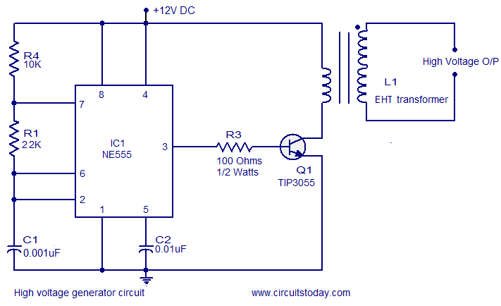
High Voltage Generator Circuit
A Boost Converter takes an input voltage and boosts it.
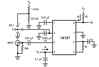
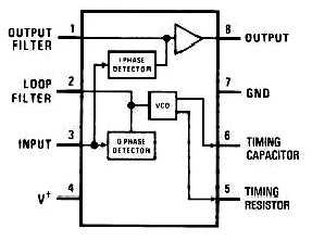
. A voltage-controlled oscillator is to verify the center frequency of the decoder. Common Block Diagram. The driver is capable of 03 A min.
Typical system block diagram N. 24 25 Next ConversionCHA Gain128 Current Output Data Next Output Data 34 PD_SCK 1234 24 25 26 Next ConversionCHB Gain32 PD_SCK 12 24 25 Next ConversionCHB Gain64 34 26 27 Fig2 Data output input and gain selection timing and control T1 T2 T3 T4 One conversion period Symbol Note MIN TYP MAX Unit. This modulator can be used to control the op power of the supply.
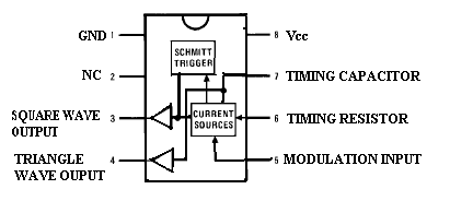
Lets take a closer look whats inside the 555 Timer and explain how it works in each of the three modes. Oscillators convert direct current DC from a power supply to an alternating current AC signal. Since then numerous companies have made the original bipolar timers as well as similar low-power CMOS timers.
In other words its like a step up transformer ie it step up the level of DC voltage while transformer step up down the level of AC voltage from low to high while decreases the current from high to low while the supplied power is same. Complete Circuit Diagram for 89C52 Controlled Circuit 60. And both the converter and the motor interfaces by the power source to provide changeable voltage frequency and current to the motor.
Working and Circuit diagram of a boost converter. Name Function 11 LVG Low-side gate-drive output. An electronic oscillator is an electronic circuit that produces a periodic oscillating electronic signal often a sine wave or a square wave or a triangle wave.
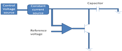
Compensated reference a com parator a controlled duty-cycle oscillato r with an active current-limit circuit a driver and a high- current output switch. The 555 timer IC is an integrated circuit chip used in a variety of timer delay pulse generation and oscillator applications. Operating Voltage Range.
- 18V to 36V PIC16LF15089. Epson provides a wide range of high-stability TCXO Temperature compensated crystal oscillator solutions. 37 Diagram Showing a 4MHz Crystal Oscillator 48.
In most applications the control input is not used so that the control voltage equals 23 V CC. Temperature compensated crystal oscillator. 25 Block Diagram of an Automatic Temperature Control System using RZK 34.
Heres the internal schematics of 555 Timer which consists of 25 transistors 2 diodes and 15 resistors. 39 Custom Factory Preprogrammed Devices. Voltage Controlled Crystal Oscillator.
Ordering information Table 1. Electric Drive Block Diagram Power Source. How It Works Internal Schematic and Block Diagram.
Double-balanced mixer and oscillator 4. Refer Block Diagram of 555 timer IC given above. Typical system block diagram L6599 636 3 Typical system block diagram Figure 3.
Block diagram Type number Topside marking Package Name Description Version SA612AD01 SA612A SO8 plastic small outline package. Thereby safeguarding the MOS transistor. Simple Packaged Crystal Oscillator MHz Programable Oscillator.
They are widely used in many electronic devices ranging from simplest clock generators to digital instruments like. For consumer applications our products focus on tiny size high accuracy and high performance. The longer the Q1 conduction time is when the duty ratio is higher the more energy the transformer retains.
Q1s gate-controlled voltage is a saw-toothed wave. Body width 39 mm SOT96-1 Type number Orderable part number. - Factory calibrated to 1 typical - Software selectable frequency range from 16 MHz to 31 kHz 31 kHz Low-Power Internal Oscillator Three External Clock modes up to 20 MHz Special Microcontroller Features.
External components are used to set the center frequency bandwidth and output delay. Ordering information 41 Ordering options Table 2. 16 MHz Internal Oscillator Block.
The schematic diagram is as follows. VTH Threshold voltage TA 25C 1225 125 1275 V TA T LOW to T HIGH 121 129 Reg line Threshold voltage line regulation. Source and 08 A min.
3513 Digitally Controlled Oscillator 䐀䌀伀尩 Modes. Controlled oscillator with an active current limit circuit driver and high current output switch. The pin is actively pulled to.
The power source in the above block diagram offers the necessary energy for the system. 310 Enabling Features andor Configuration Settings Not Available in ClockBuilder Pro for Factory. Derivatives provide two or four timing circuits in one packageThe design was first marketed in 1972 by Signetics.
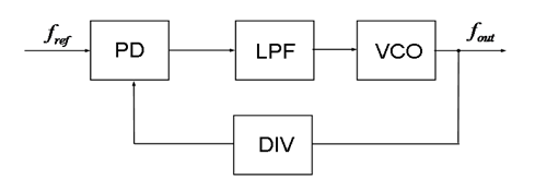
The phase detector and VCO form a phase-locked loop PLL when the PLL is locked and the input signal amplitude exceeds an internally pre-set threshold a switch to the ground. The circuit block diagram of the switching power supply is as follows. Sink peak current to drive the lower MOSFET of the half-bridge leg.
Voltage Controlled Oscillator Usage Of Vco Working And Application
![]()
Transistor Oscillator Circuit Working Types Its Applications
Variable Frequency Oscillator Circuit With Schematic
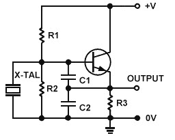
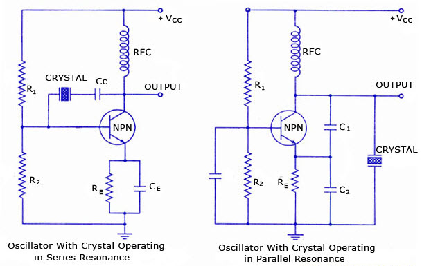
Overview Of Crystal Oscillator Circuit Working With Applications
Voltage Controlled Oscillator Usage Of Vco Working And Application
Voltage Controlled Oscillator Usage Of Vco Working And Application
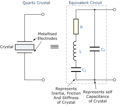
Overview Of Crystal Oscillator Circuit Working With Applications

Ne566 Function Generator Voltage Controlled Oscillator Vco Circuit Electronic Circuit Projects Function Generator Circuit Projects

Voltage Controlled Oscillator Usage Of Vco Working And Application
Voltage Controlled Oscillator Usage Of Vco Working And Application
Voltage Controlled Oscillator Usage Of Vco Working And Application

Voltage Controlled Oscillator Vco Voltage Controlled Oscillator Electronics Circuit Electronic Cables
Overview Of Crystal Oscillator Circuit Working With Applications

Ne566 Function Generator Voltage Controlled Oscillator Vco Circuit Voltage Controlled Oscillator Function Generator Linear Function
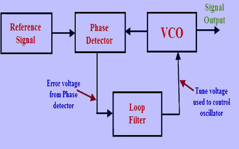
Phase Locked Loop Operating Principle And Applications

Voltage Controlled Oscillator Vco Circuit Voltage Controlled Oscillator Electronic Circuit Projects Circuit

Voltage Controlled Oscillator Vco With A 555 Timer Chip Voltage Controlled Oscillator Timer Electronics Circuit


Komentar
Posting Komentar